")
")
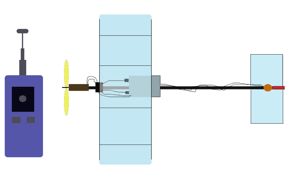
Whatever complete seemed micro-airplane, to revive it cans only remote control. In turn, in your hands will be steering control.
I think it would be superfluous to describe those pleasant feelings, which feels the pilot.
And it's not a computer game, on the contrary the real flight real micro-plane…
So, let's look at how we can construct the electronics for all of these.
In this article we consider a transmitter, with him I would recommend to start.
The heart of the transmitter is microcontroller PIC12F629, and it generates, codes, and modulates the signal.
But how is the formation of a signal and its encoding? Let's face it.
Our construction uses a multi-channel transmission of information, in which all the channels are multiplexed in one by means of encoding. For this uses pulse phase modulation, denoted by the letters PPM (Pulse Phase Modulation)
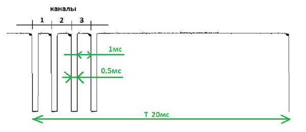
PPM signal has a fixed length of the period T = 20ms. This means that information about the positions of knobs on the transmitter goes to the model 50 times per second that determines the performance of control equipment. Typically, this is enough, because the speed of pilot reaction to the behavior of the model is much smaller. All the channels are numbered and transmitted sequentially. The value of the signal is determined by the time interval between the first and second pulse - for the first channel, between the second and third - for the second channel, etc. The greater the gap, the wider the pulses in the receiver for the channel, and the greater the current in the load (actuator, motor). The range of change of the time period when moving the joystick from one extreme to the other is defined from 0.5 to 1.65ms. A value of 1ms corresponds to the average (neutral) position of joystick (knob). Duration of interchannel pulse is about 0.5ms.
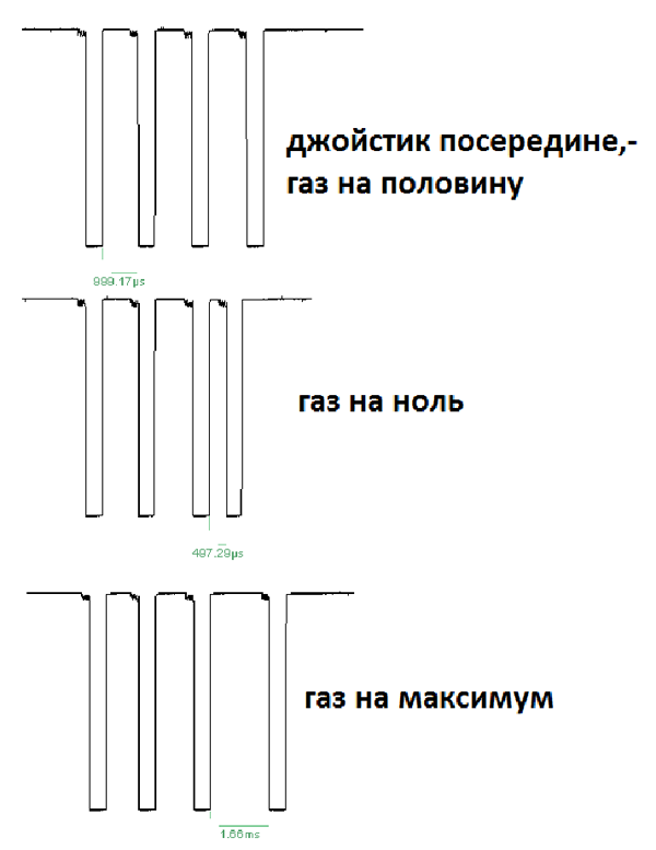
- Joystick in the middle - half the gas
-
Gas at zero
- Gas at a maximum
This structure of the PPM signal is standard for all manufacturers of RC-equipment. The values of the middle position of the knob from different manufacturers may vary slightly.
Consider the work of circuit.
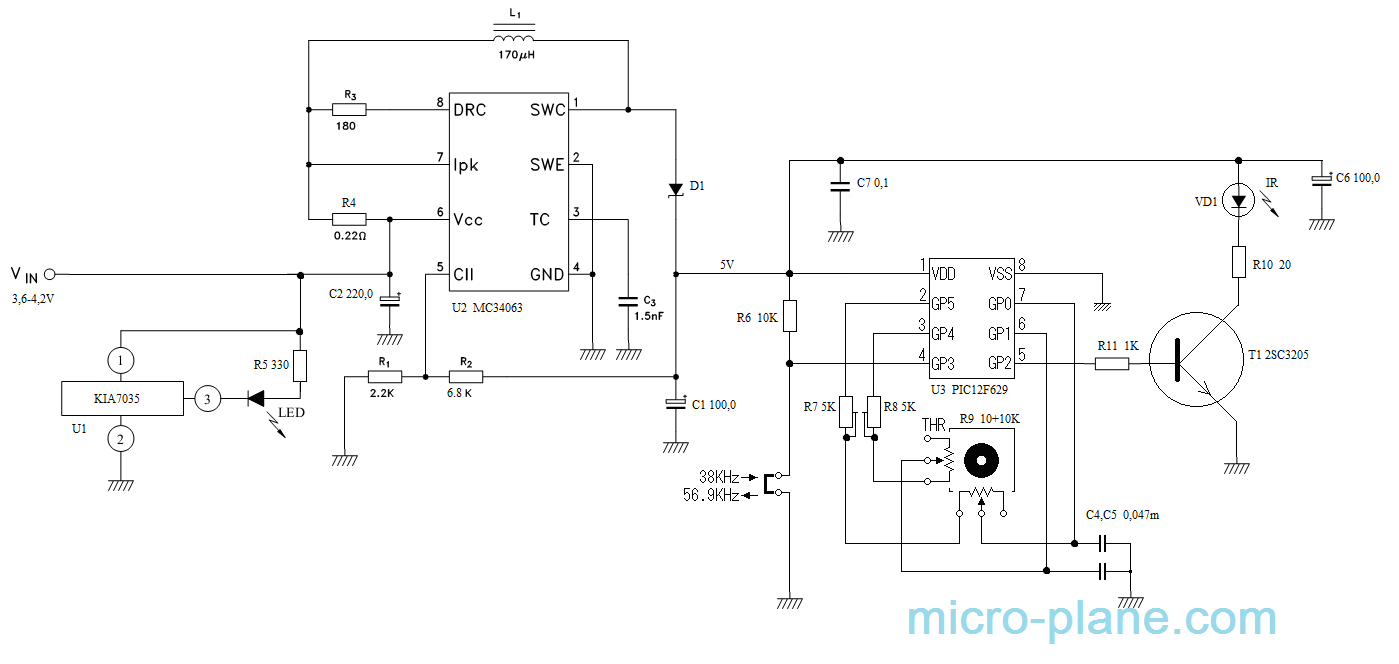
PIC12F629 microcontroller does not have an internal analog-digital converter (ADC), and a curious reader might wonder: what now supports analog joystick for smooth adjustment of engine speed and angle of the rudder? It is very simple.
On pins 2 and 3 of the microcontroller (MC), in turn, periodically arise pulses the log. 1, on the leading edge of which through the resistors R7, R8, R9 are beginning to charge capacitors C4, C5, from the value of the resistors (the angle of rotation joysticks) depends on the time during which the capacitor is charged to a specific value, when the level of the inputs 6 and 7 MC can be a log. 1. Then the capacitors are discharged, and it happens all the time while on the MC is supplied voltage. From the time of the charge of these capacitors depends on the duration of "pauses" between the "channel" pulses. So is implemented the transformation analog to a digital signal, as well as its encoding. With this understood, the modulation remains.
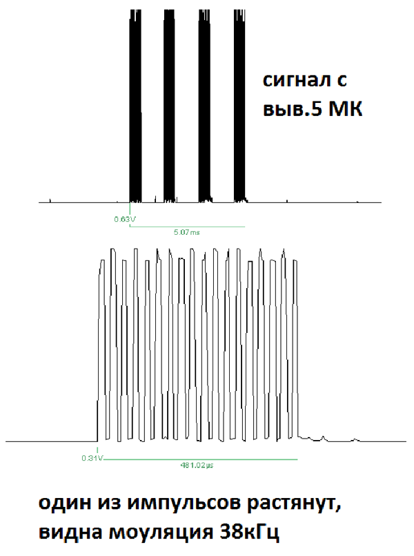
To catch a formed and coded signal in the infrared (IR) receiver not enough to simply connect to the proper terminal MC IR LED. The fact that the integrated IR receivers for to increase noise immunity, as well as to increase the sensitivity is implemented the input filter, bandwidth of which is narrowed, with different receivers it is different. Therefore, the useful signal is not yet ready it must be modulated, what makes the MC. By log. 1 at the input 4, he gives a signal modulated frequency of 56.9 KHz, at log. 0 - 38 KHz
-
Signal from the output 5 MK.
-
- One of the pulsed is stretched, we can see the modulation 38kHz.
With the work of coders we are ready, go to the power circuit.
Here, too, nothing complicated, on chip U2 is implemented step-up DC-DC converter that is required to maintain voltage at a constant level of MC 5 volts, despite the gradual discharge lithium battery supply. And to avoid a deep discharge of battery the circuit has a discharge indicator on chip U1 that lights LED at supply voltage 3.5 volts.
About the materials:
Microchips MC34063 and PIC12F629 are very common, and can be purchased on the radio market.
KIA7035 can be taken from the card faulty DVD player, the microchip is in the chain of reset the processor. If you use a lithium battery from the mobile phone, you can not solder in the chip U1, because this battery contains a controller that protects deep discharge. But in this case, there is a risk to break the plane, if suddenly the controller turn off the battery and you will lose the control.
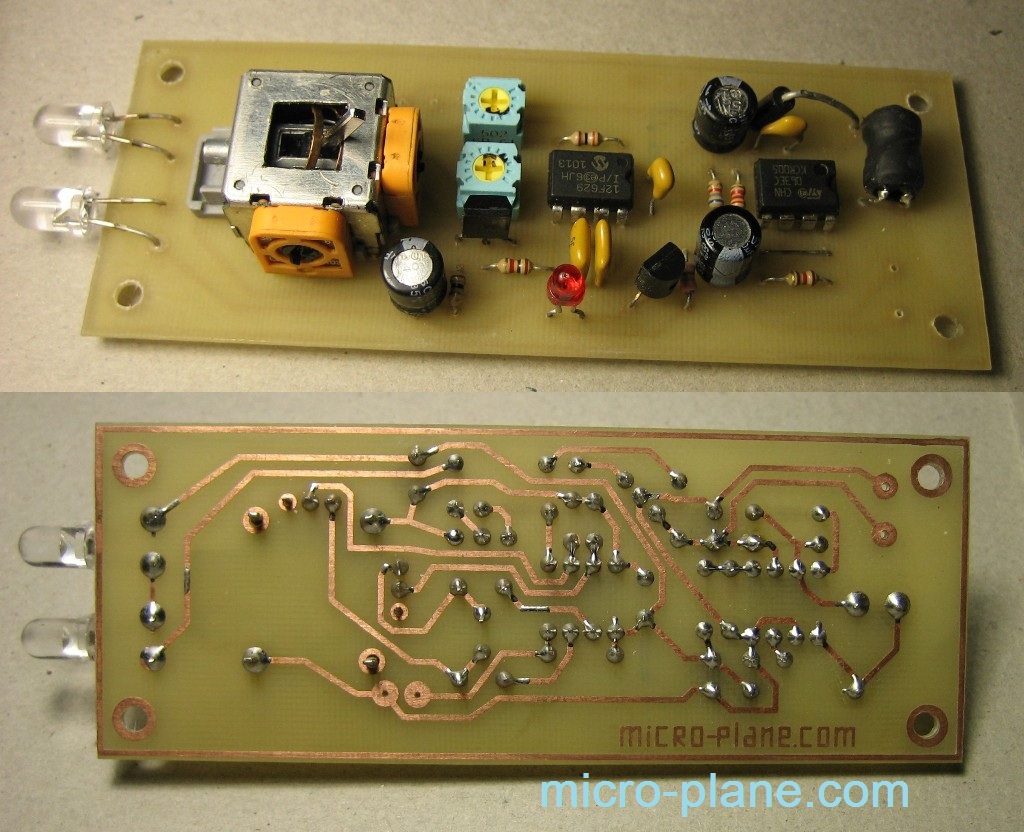
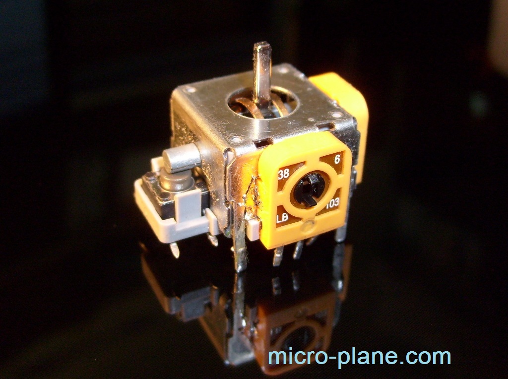
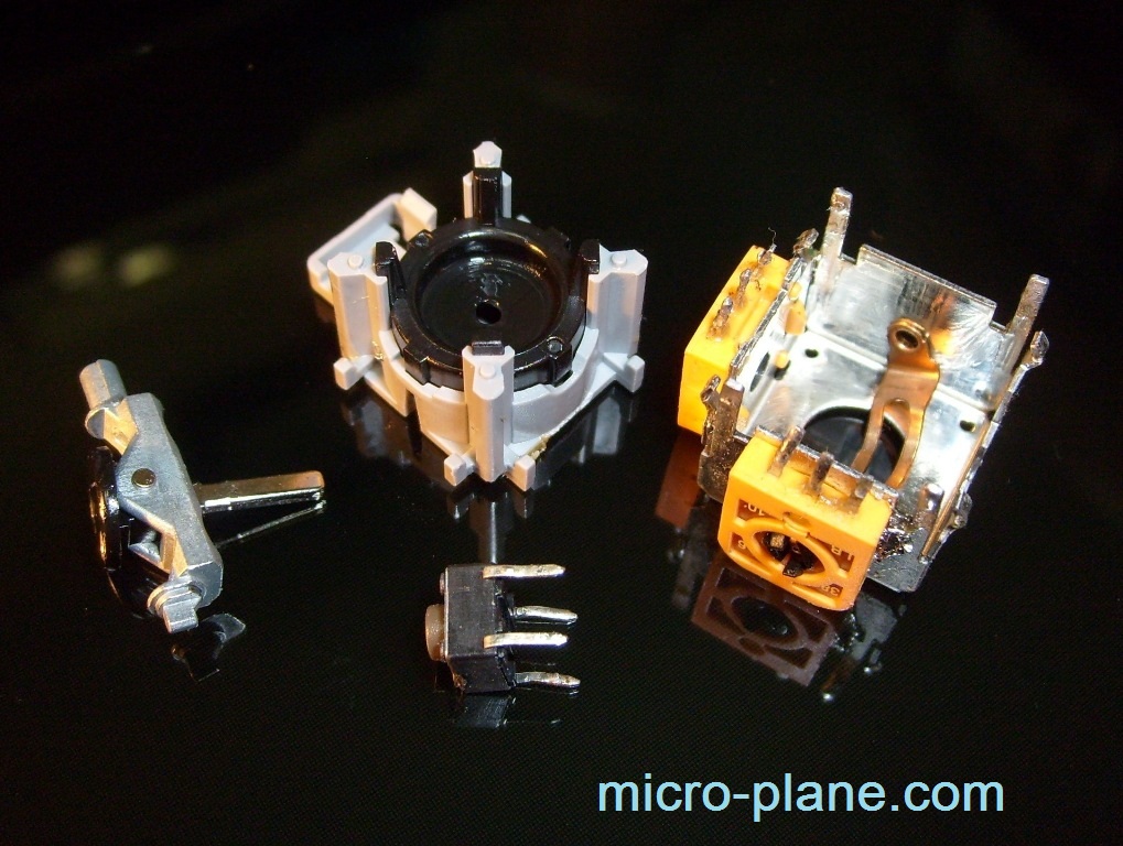
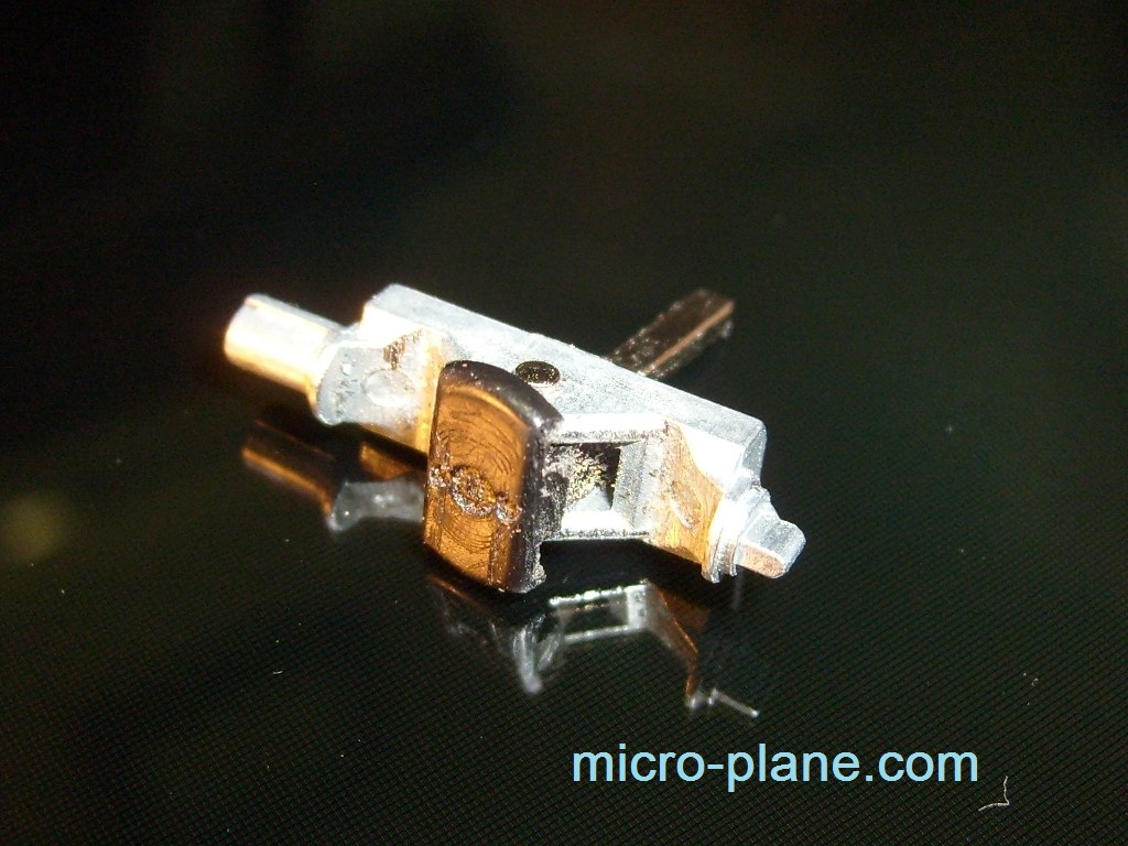
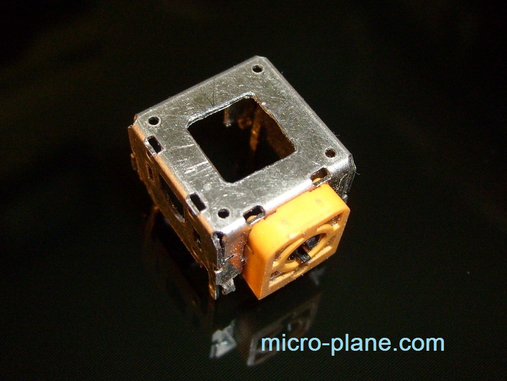
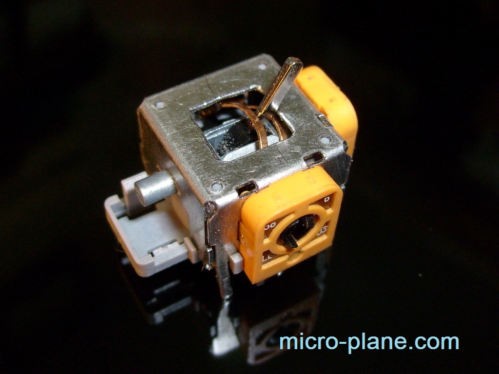
As a R9 is used standard two channel resistor out from analog joystick of PSP attachment. Only have to modify it a bit with a file to an upper window was not round and square, which will produce greater manipulation of the right-left, up and down. You will also need to disassemble in order to whittle away the plastic guard, this will fix the "trigger" for zero and maximum. All the improvements are visible in the photo below.
It is better to use film capacitors C4 and C5. Diode D1 - any pulse, the current no less than 200 mA. As a T1 can be used any bipolar transistor NPN medium power structure, or even N-channel field. Choke L1 - anyone inductance of 100-200 mg, but for a current of 200 mA.
Correctly assembled circuit begins to work immediately and to set up almost does not need. Optionally, you can more accurately set the voltage converter with resistor R1.
Engines trimmer potentiometers R7, R8 should be set to the middle position, a more precise their position can be found by using ready-made receiver.
The microcontroller is programmed without any features, you need only to choose the type of programmer management program, all the checkboxes is displayed in the firmware, and do not forget to consider the amount of calibration from the microcontroller (the last byte), then to add it to the firmware. More about this in the part "programmer".