")
")
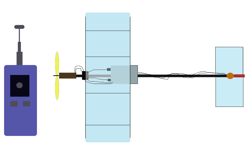
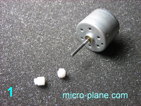
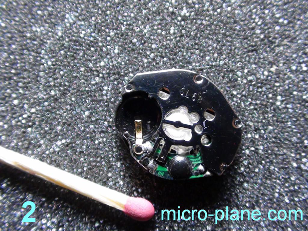
That the micro plane may obey the rudder bar and turn the «tail» we need the device that transforms electric signals from the receiver into the mechanical energy – something like muscle. Such device is called actuator. You can easy make it. You don’t need any costly details. All we need – engine with gears, optical systems from a disk-drive mechanism, machinery of the quartz wristwatch (photo 1, 2, 3). All these details can be in defective condition.
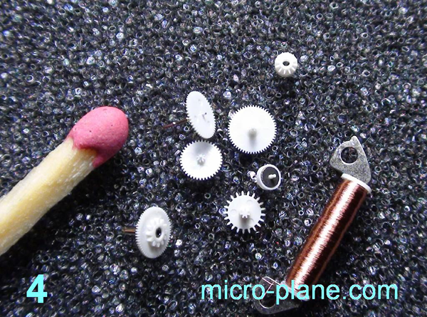
Okay, did you destroy your DVD player and wristwatch? Let us begin then. Disassemble accurately machinery of wristwatch. We need two details – motor winding and magnet-rotor. Don’t be in a hurry to throw out the gears, we need them also (photo 4) .
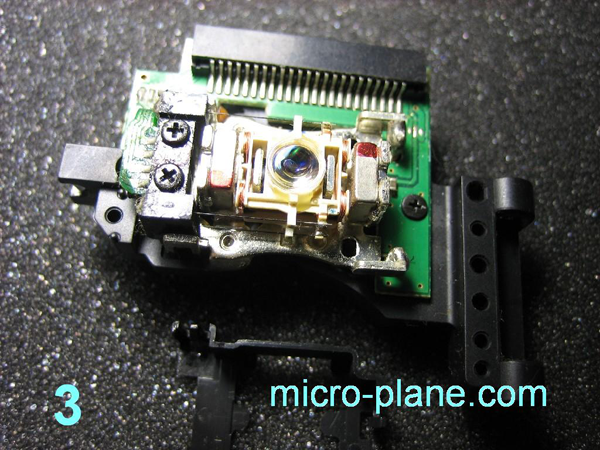
In the winding is used the wire that is thinner than human hair! As a rule diameter is 0,02mm and the resistance 47 ohm/m. Handle it cautiously, the slightest force and it is torn. It is very important do not lose the end of the wire and do not damage the winding itself by the disassembling. The wristwatches are maybe the only source of micro magnets, the size of which can be used in actuator for plane by weight smaller than one gram. At the same time this magnet is very strong. I recommend you insistently make watchmaker acquaintance . If you don’t do it, you will suffer from the envy, as you will looking on photo 5 :).
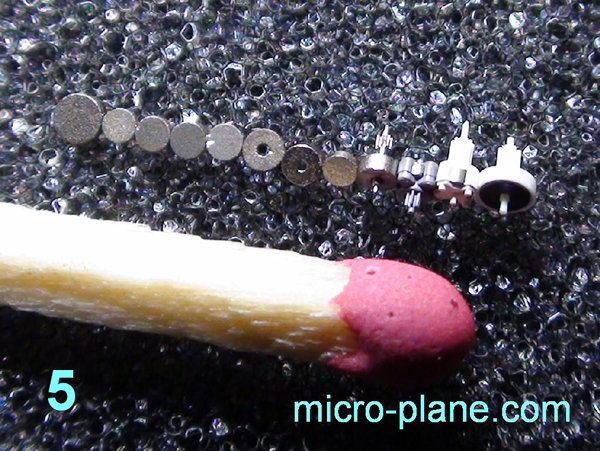
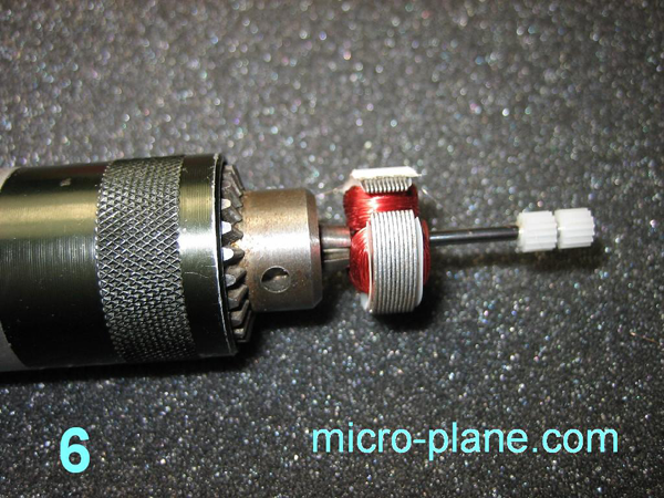
As you can see the magnets are different in size and only some of them have an axial aperture. Presence of aperture facilitates our structure process of actuator, and this article were practically in 10 times smaller. Whereas the «holed» magnets are scarce, in our article we consider the structure process of actuator using monolithic magnet. It is better to start, perhaps, from making of tiny circular electromagnet; it is convenient to wind on good polished base, here is useful to us the engine from the photo №1, its shaft is polished brilliant. You have to got to disassemble the engine, to pick-off rotor and to press it into holder of the drill. Get two gears on the shift, they make up the form of future electromagnet, between them must be a distance roughly 0,7mm (the wide of future electromagnet) (photo 6).
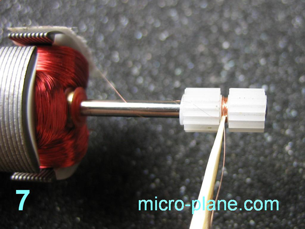
Make fast using peace of sticky tape the beginning of the wire on the holder, it should be wired carefully, don’t forget that the wire is thin. It is better to supply the drill from the controlled power unit. We set up such voltage by which the shaft is turning rather slow, the speed is convenient to regulate by pressing the finger on the bit holder, this provide good reaction in case for example the wire is got tangled and you have to hold up rapidly the winding. Oh yes, I forgot completely, we need to obtain the resistance of the winding in the range 150-240 ohm. It isn’t difficult to calculate the length of the wire if we know its resistance on 1 meter. I took the wire 4 meter length with resistance 47ohm/m. The winding turned near 190ohm. Okay, did you already wind? Then carefully by the instrumentality of pointed toothpick put on the wire end a little superglue, thereupon wind the rest of wire with drop of glue on the winding, leave the length about 1-2 cm, that prevent its unrolling (photo 7).
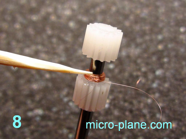
Further you should move the last gear near to the end of shaft and by the instrumentality of the same toothpick, carefully put on the uncovered part of winding layer of glue, together don’t glue the shaft! (photo 8)
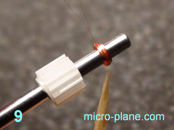
When the glue is grabbed, you should with an effort put together the gears, it gives the compact form of our winding. The same we do with the other side of winding, moving the second gear neat to the bit-holder (photo 9).
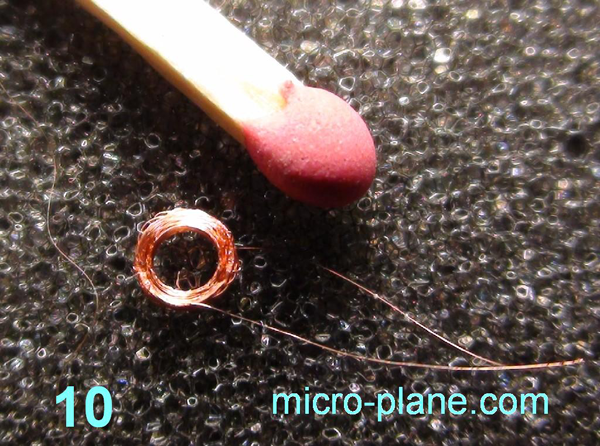
When the glue is grabbed, again put together the gears, squeezing the winding rough on 2-3 seconds. Then take off the last gear and slow move the winding endwise by instrumentality of the second gear, as the winding comes to the end of shaft it effortlessly comes off the shaft (photo 10).
The electromagnet is still not fully glued and the coils can easy part, therefore take the both and of the wire, let fall a drop of glue on the wire and without delay blow off the rest of glue until it is grabbed. Such thin applied glue get dry quickly, 5 second and the winding is finished. Now the worst part, it should be tinned, but don’t tear off it. Using the cut and try method is found the perfect method how to do it: we take a peace of tinned foil-coated glass-fibre plastic, advisable with two isolated one from am other fields. And lean the wirings against the glass-fibre plastic, carefully, by instrumentality of the clean bit of soldering iron «solder in» their into the surface of tinned glass-fibre plastic, don’t forget to add the colophony. As has showed an experience, the heated soldering iron quickly burns down the enamel from this thin wire, and owing to the fact that the wire is «swimming» in the melted solder, it at once tinned and joins together the fields of glass-fibre plastic (photo 11).
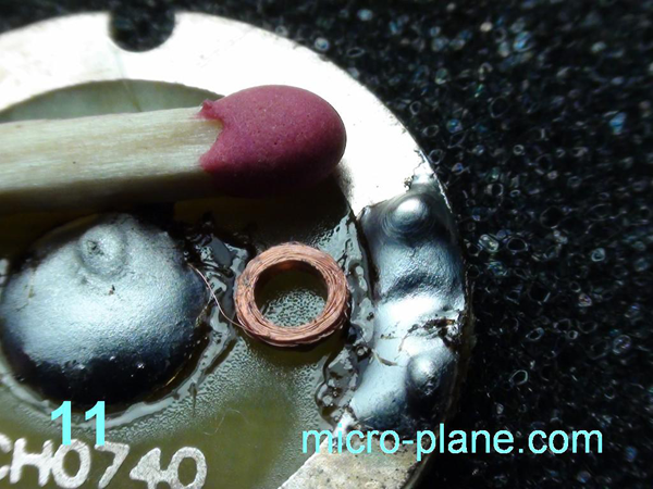
Now we can measure the resistance of winding, thereby we are convinced of its integrity, otherwise to continue is meaningless. Further we have to tin to the winding the wires of bigger diameter, this operation is also very complicated and threatens the break of wire. There is nothing like doing this way: we put the ring of winding on the toothpick, glue to the ring two tinned wires (photo 11).
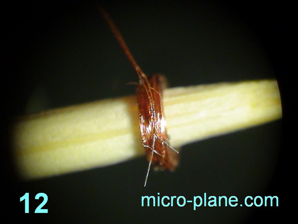
When the glue is grabbed, we have to wind with thin wire of the electromagnet more thick «interface» wire and to tin their (photo 12).
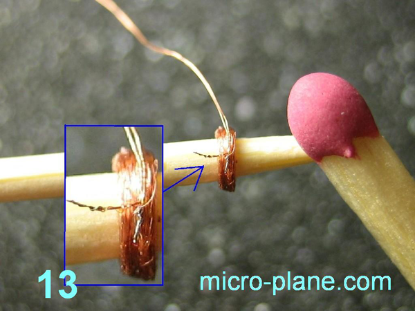
Squeeze the wires to the winding, part it in opposite sides, that they may not be closed, after the sizing the electromagnet is finished. Now we start to do a slewing gear that is fixed on the fin. For it we need an optical system as on the photo 3. We take off the brass twigs, those hold the lens, they are enough resilient and good fit in the role of hinges. Bend the end of the twigs in the ring diameter roughly 0,3mm. One couple of coil will be enough (photo 14).
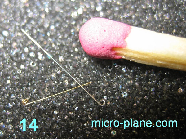
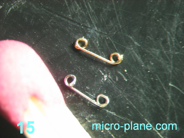
The second coils need to do on the distance roughly 4mm. (photo 15).
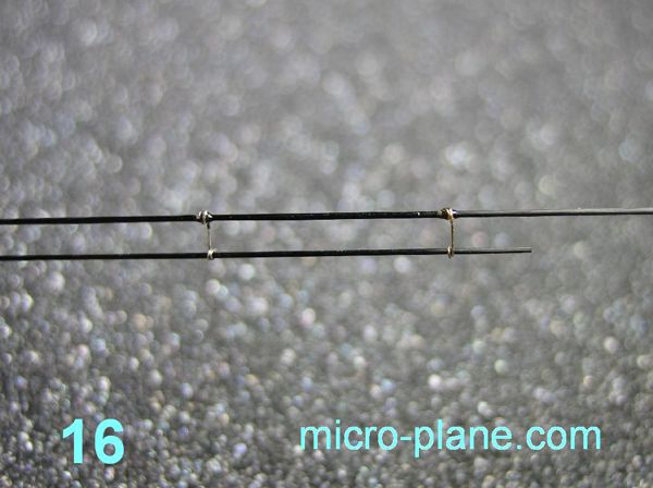
Then we need carboxylic twigs diameter 0,28mm. Connect two twigs by instrumentally of the brass coils that you made, glue the coils to one of the hinges so that the second twig could free turn in the hinge (photo 16)./p>
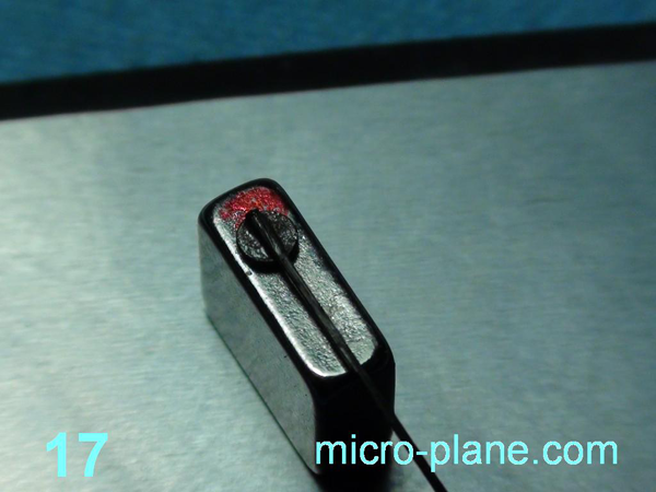
While the glue is getting dry we deal with the magnets. On this stage we need magnet from the optical system; you can take him off using an office knife and tear away the glue. It will serve as «delimiter» of the magnetic field to the north and south. I shall explain: that the actuator will turn in both sides with the same effort, the small magnet from the wristwatch should be placed inside the electromagnet - poles towards the butt ends of last one. Understand? No? Than you will understand later The magnet from the optical system has two poles those are located on both sides with the largest area. Thereby, if to it butt end put the small magnet from the watch than the last one will gain the orientation - we need. Now it remains only to glue to him the carboxylic twig, sticking the orientation along the butt end (photo 17).
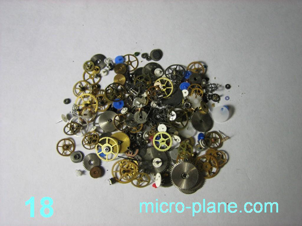
Did you already make the acquaintance of watch repairer? If yes, than you surely have large quantity of diverse gears from quartz/mechanical wristwatches (photo 18).
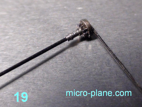
We choose the gear with the axis in the form of tube with inner diameter 0,25-0,3mm, put in it the carboxylic twig and glue on the middle of the magnet. Thanks to the gear we kill two birds with one stone: easy and simply find the center of the magnet and, by itself, set the magnet perpendicularly to the twig, so that during the twig rotation the magnet will turn without a wobbling (photo 19).
Now we pass the twig with the magnet through our construction with hinges, those are already glued, them we put peaces of wire covering on the turning twig, and thanks to them we limit the twig free play along its axis. We glue horizontal twigs. For reduction of weight we can split them lengthwise.
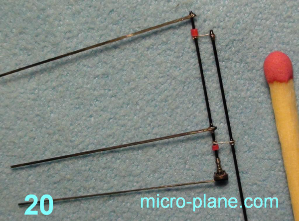
Pay attention: the horizontal elements must be parallel (photo 20).
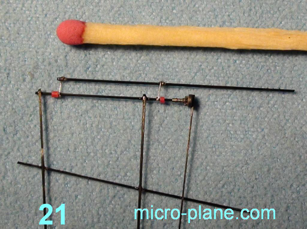
We add a vertical detail (photo 21).
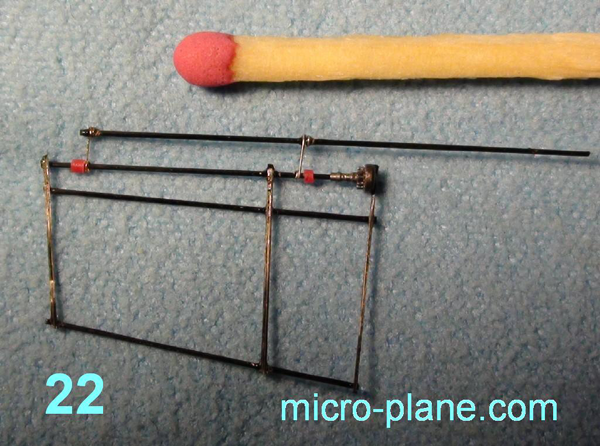
The last twig we glue nearly to the hinges, on him, substantially, will be last the magnet. When the glue gets dry we cut all unnecessary (photo 22).
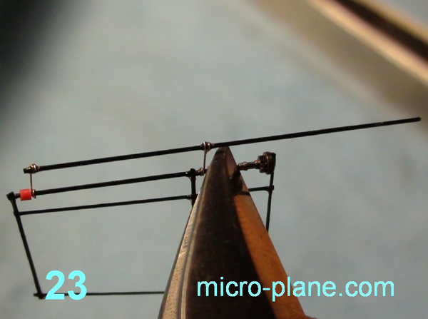
Now the crucial point – it needs to move off the gear without contact breach the magnet with lower twig. Best of all to do this operation using sharp side cutter (photo 23).
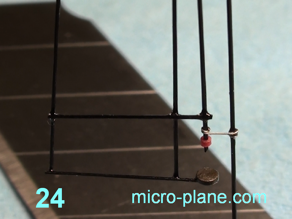
There now our construction of slewing gear is finished. We can make sure of right magnet centering turning it on «nonexistent» axis (photo 24).
There is only one little thing left. We set and fasten the electromagnet winding by instrumentally of twigs and a drop of glue. Congratulation! The actuator is finished! Photo 25, 26, 27.


It is remained only to finish construction of the fin, cover with film. But it is theme for another article – «glider».
Wait for your question on Forum..